Содержание
- I NTRODUCTION
- I NTEGRATED M ETROLOGY U NITS
- I DENTIFICATION AND T EST M ETHODS OF M EASUREMENT
- LABORATORY I MPLEMENTATION
- I NDUSTRIAL I MPLEMENTATION
- СONCLUSION
Аннотация
В статье рассматривается процесс разработки локальной системы управления технологическим процессом дозирования, приводятся: алгоритмы работы, изображение мнемосхемы и окон на HMI-терминале, возможности дальнейшего использования готового решения.
Ключевые слова: локальные системы управления, автоматизация, технологические процессы, типизация, станция затаривания
Введение
Использование локальных систем управления, поставляемых комплектно с оборудованием, обеспечивает ряд преимуществ:
– заказчику подобного решения не придется выделять дополнительные средства на разработку и наладку алгоритма управления данным оборудованием;
– локальные системы управления являются самодостаточными, и при использовании комплектных решений не потребуется отдельно закупать и устанавливать контроллерное и HMI оборудование;– возможна интеграция локальных систем с вышестоящей АСУ. При таком подходе управляющий алгоритм по-прежнему выполняется в ПЛК локальной системы, что позволяет снизить нагрузку на контроллер основной системы управления.
– возможно создавать системы управления малых производств или технологических установок не требующих создания всех видов обеспечения, относящихся к АСУТП [1].
Описание объекта
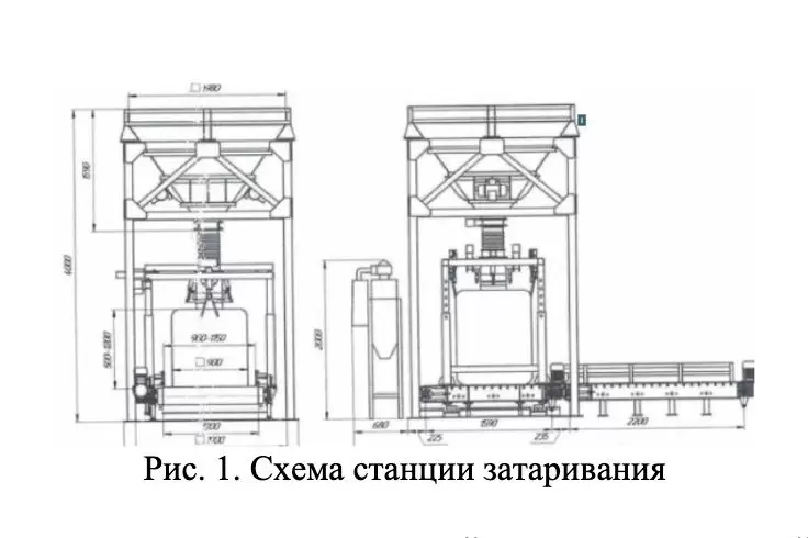
Станция затаривания (рис. 1) предназначена для загрузки сыпучих материалов в мягкие контейнеры типа «Биг-бэг». Данный вид тары является на сегодняшний день одним из самых экономичных видом упаковки для многотоннажных грузов.
Биг-бэги успешно используются в логистических схемах транспортировки, складированияи хранения сыпучих продуктов угольной, химической, сельскохозяйственной, строительной, пищевой и других отраслей промышленности. Станция с комплектной локальной системой управления может использоваться как в составе линий упаковки сыпучих материалов, так и в качестве самостоятельной автономной технологической единицы.
Алгоритм работы
В системе предусмотрено 2 режима: ручной и автоматический. Выбор режима осуществляет оператор при помощи переключателя на ШУ.
В автоматическом режиме перед началом работы оператор надевает вкладыш контейнера на загрузочный патрубок после этого нажимает кнопку «Пуск дозирования» на ШУ. В этом режиме работы механизм прижима фиксирует загрузочную горловину контейнера, начинается цикл дозирования, происходит тарировка контейнера, обнуляется значение веса. Затвор находится в закрытом положении, после тарировки мешка включается система наддува на несколько секунд, открывается задвижка на аспирационную систему, затвор открывается и начинается дозирование материала. Подача материала в весовой бункер вначале осуществляется «грубо/быстро», затем «точно/медленно». Смена грубого дозирования на точное происходит изменением величины открытия затвора. При достижении веса на весовом конвейере подача материала полностью прекращается. Закрывается задвижка на аспирационную систему, механизм прижима открывается. Срабатывает механизм снятия фиксации мешка. Во время подачи материала работает система аспирации.
Контейнер перемещается с весового конвейера на накопительный. При пересечении биг-бэгом датчика концевого положения в конце транспортировочной линии, конвейер останавливается. Цикл завершается.
Нажатие кнопки «Стоп» во время автоматического цикла останавливает затаривание на паузу. Нажатие кнопки «Пуск» возобновляет процесс. Нажатие кнопки «аварийный стоп» полностью останавливает цикл с его завершением.
Для затаривания нового мешка оператору необходимо вновь надеть вкладыш контейнера на загрузочный патрубок и нажать кнопку «Пуск дозирования».
В ручном режиме для управления системой затаривания предусмотрены соответствующие кнопки управления практически для всех узлов: загрузкой весового бункера, наддува мешка, вибраторов, перемещения контейнера и прочими в зависимости от комплектации системы.
При нажатии оператором кнопки «Пуск дозирования» в ручном режиме, осуществляется подача материала «точно» с низкой скоростью. Для быстрой «грубой» подачи необходимо удерживать кнопку «пуск». Для прекращения подачи материала оператору необходимо нажать кнопку «Стоп дозирования».
Все сигналы с локального АСУ интегрированы в пределах требуемого функционала с системой АСУТП заказчика. На HMI панели оператора Weintek 7’, расположенном на шкафу управления (ШУ), отображается текущее состояние станции затаривания.
Контроль и управление оборудованием станции затаривания осуществляется оператором посредством пульта управления. Пульт управления реализован на базе 7” HMI-терминала Weintek cMT2078X, с использованием среды разработки EasyBuilder. Данный программный комплекс состоит из визуального редактора проектов и набора утилит, решающих различные задачи. При разработке проекта организовано взаимодействие панели оператора с ПЛК и визуализация элементов автоматизируемой системы на экране
На пульте управления (рис. 2) представлена мнемосхема с отображением всех агрегатов и материальных потоков данной технологической схемы (рис. 2 а).

Рис. 2. Мнемосхема системы управления станцией затаривания (а); всплывающее диагностическое окно общесистемных признаков станции затаривания (б)
Отображение информации о текущем состоянии каждого агрегата, входящего в состав отображаемой схемы, осуществляется посредством цветовой индикации мнемонического изображения этого агрегата в соответствии с признаками, формируемыми в контроллере по результатам обработки сигналов с датчиков (рис. 2 б).
Детальная информация о текущем состоянии агрегата, причинах его неготовности или аварии дается в виде текстовых сообщений на всплывающих диагностических окнах, вызываемых по команде оператора.
На диагностическом окне (рис. 3) текстовые сообщения (аварийные или информирующие признаки) выделяются черным цветом на фоне прочих сообщений, пиктограмма возле сообщения окрашивается в красный цвет для аварийных и в зеленый цвет для информирующих (рис. 3 а).

Рис. 3 Всплывающее диагностическое окно вибраторов (а); диагностическое окно администрирования (задания уставок) (б)
В проекте реализована система доступа с различными правами просмотра и управления для оператора станции затаривания, инженера КИПиА и технолога. Так, технолог, обладая правами администратора проекта имеет доступ к изменениям уставок открытия задвижки бункера при различном заполнении мешка и настройкам таймеров открытия задвижки аспирации, работы и паузы вибраторов, останова накопительного и весового конвейеров по оптическому датчику (рис. 3 б).
Вывод
При разработке программ логического управления за основу взят подход типизации программных модулей [2-5], которые выполнены в виде функциональных блоков.
Такой подход позволит в будущем тиражировать разработанную систему для однотипных станций затаривания без необходимости нового проектирования и разработки программного обеспечения.
Автор статьи: технический директор Горб Дмитрий Сергеевич
Weighing Systems with Integrated Metrology Units
Abstract—The paper considers a type of weighing systems with built-in metrological blocks that implement identification and test methods of measurement with a multivariant structure. The functional scheme of multivariant measuring system with built-in metrological blocks is presented. The differences between the systems with embedded metrological blocks fundamentally from traditional measurement systems are analyzed. Realization of automated laboratory metering installation and industrial complexes of automatic metering which depending on a complete set can include the considered multivariant metrological blocks for identification of metrological characteristics of measuring instruments on the basis of natural-model approach and multivariant systems are described. Industrial implementation is considered on the example of a batcher corresponding to GOST 30124-94 designed for batching of bulk materials and an automated control system for multicomponent batching which together with the suggested built-in metrological blocks have advantages over their analogues in terms of accuracy and maintenance costs.
Keywords—weight measurement, weighing, test methods, burdening, multivariate
I. I NTRODUCTION
Weighing systems have a special place at any production. If the quality of commercial accounting is clearly expressed as an economic effect, it is harder to evaluate the technological one, as errors made at different stages of the technological process due to incorrectness of incoming information in the control systems have a great impact on multi-stage production. In this case, the accuracy of weight-dosing systems depends on the total error of weight measurement, which mostly depends on methodological factors and some extent on technical factors and after that on the control algorithms themselves.
II. I NTEGRATED M ETROLOGY U NITS
Solving technical problems is not enough to solve the problem of improving the accuracy of the measurement system, such as increasing the sensitivity of elements, the digit capacity of transducers, the quality of signal transmission, etc. The operation of measurement subsystems is characterized by essentially nonlinear changes in time and requires a special solution to the issues of coordinating data processing algorithms with the transformations affecting the total measurement error. This requires the use of built-in identification and test metrological units [1,2].
The effectiveness of such built-in metrological units lies not much in automation of such procedures as registration, collection and transmission of direct measurements for processing as in providing fundamentally new opportunities of conducting the measurement experiment. Namely, the experiment can be conducted with active influence on the measurement object in accordance with adaptive optimal plan of a particular measurement task, hardware and numerical methods of filtering and correction of errors can be used. It can be allowed the principles of invariant and complexing can be widely applied, operator intervention in the course of the experiment in the dialogue mode, etc. [3-5] The use of these features allows you to get more complete information about the object and contributes to a significant increase in the efficiency of measurement processes. Thus the actual issues of development and improvement of automated systems of technological measurements and their adaptation to a specific measurement object is the introduction of metrological units, solving the problems associated with the
definition of standard and real metrological characteristics of individual traducers and systems as a whole. It is necessary to calculate measurement errors; improvement of accuracy, reliability and reproducibility of measurement results; determination of the dynamics of measurement errors for the purpose of planning metrological operations, as well as automation of metrological tests, including operational verification and metrological diagnostics of modern complex measurement and information-measuring complexes.
definition of standard and real metrological characteristics of individual traducers and systems as a whole. It is necessary to calculate measurement errors; improvement of accuracy, reliability and reproducibility of measurement results; determination of the dynamics of measurement errors for the purpose of planning metrological operations, as well as automation of metrological tests, including operational verification and metrological diagnostics of modern complex measurement and information-measuring complexes.
III. I DENTIFICATION AND T EST M ETHODS OF M EASUREMENT
The solution of the problem of calculating metrological characteristics of measuring channels of analog-to-digital complexes is important for the practice of specific measurements [6-8]. There is a known approach to calculate the normalized metrological characteristics of the system according to the established metrological characteristics of individual measuring traducers. Methods based on deterministic approach to rationing only the limit of tolerable values of the basic and additional error no longer can provide verification of measuring instruments with the required degree of reliability. The solution of this problem are not fulfilled as a statistical evaluation problem proceeds, as it is well known,
from a number of assumptions (hypotheses) regarding the properties of errors, which in most cases of practical measurements, especially in industrial production conditions.
The tasks of experimental determination of static and dynamic metrological characteristics are far from being solved. Most methods for determining the metrological characteristics of measuring instruments are based on methods of identification and some sections of calculation mathematics [9, 10]. There are known difficulties in applying these methods, for example, due to the incorrectness of the calculating procedures. It is worth noting that the problem of identification of metrological characteristics in metrology has specific features, because the determining (input) factor in measurement systems is an unknown quantity and identification has a special input test action, reproducible with a given accuracy. As a result, significant difficulties arise in the implementation of test effects when determining such physical quantities as temperature, pressure, flow rate, substance composition, etc., as well as for most physical quantities, especially in wide ranges. That is why the method of element-by-element verification of measuring systems is widespread in practice.
Test methods of measurement are an important tool for solving tasks, especially for modern automated systems. These methods have been adopted as prototypes in the development of new methods for measuring such physical quantities as the mass of loads and dosed materials, the flow rate of liquid and gaseous substances, etc. Models and algorithms of identification-test technological measurements are based on the concepts of the general scientific-applied direction «Variances» [11].
For example, there are the following types of multivariant structures: 1. Multivariant structure of the object type, which is most often embodied in the form of full-scale model blocks, so necessary for production and research automated systems. 2. Multivariant structure of recursive-layered type, which corresponds, in particular, to a multivariant filter of exponential smoothing of the first, second, third and so on orders. 3. Multivariate structure of channel-type, underlying multichannel active systems with origins in stimulated man-machine interaction. 4. Combined multivariant structures.
Multivariant structures are fundamental to the direction of multivariant technological measurements, means and systems, especially in the form of multivariant methods and measuring methods and primary measuring transducers.
In general, the structure of a multivariant measuring system with built-in metrological blocks is shown in Fig.1 Authors and Affiliations
The guiding principle of multivariant technological measurements is formulated as follows: there is no anyone, allegedly optimum variant of measurement of any technological quantity and in the majority of situations practically necessary the complex realization of many variants of technological measurements with their effective mutual combination and interosculation on all functions and kinds of maintenance.
To improve metrological support in the structure of the measuring system two subsystems are allocated: acquisition-measuring and calculation-measuring. First one is used for direct perception of measured technological parameters and their transduction into measuring information signals. This subsystem correlates with samplers, communication lines and other devices.
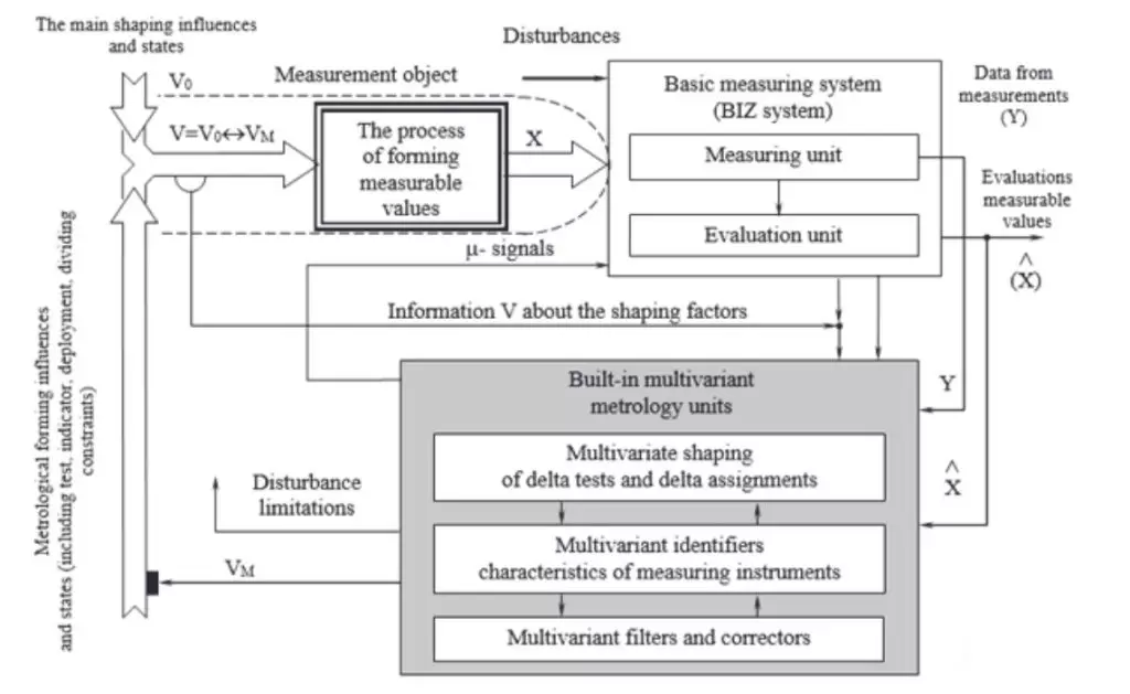
Schematic diagram of a multivariant measuring system with integrated metrology units
Second one is a recalculation models, smoothing and restoring filters and other operator converters are used for processing primary signals with the purpose of reliable evaluation of actual values of technological parameters. Second one is a recalculation models, smoothing and restoring filters and other operator converters are used for processing primary signals with the purpose of reliable evaluation of actual values of technological parameters. Automated systems of technological measurements with built-in metrological units are fundamentally different from traditional measurement systems. It is because along with the known metrological effects, as a rule, at the level of exemplary LQIOXHQFHV ɏɨɛɪ DQGVLJQDOV -signals) directly to the inputs of basic measuring instruments in IIM special restrictions and metrological forming effects (including test, indicator, deploying etc.) directly on measurement objects (on the formation process of measured quantities).
The basis of methodological support for the IIM and VMB is the apparatus of full-scale mathematical modeling [12, 13]. It is with limit variants in the form of purely full-scale experiment on the one hand and purely mathematical modeling on the other hand. As well as robust procedures of multisample formation and analysis of full-scale and half-surface data under conditions of normal operation of measuring instruments and limited active experiment.
IV. LABORATORY I MPLEMENTATION
To solve training and research tasks based on the proposed methods and concepts we developed an automated laboratory unit based on the physical model of the dispenser Fig. 2
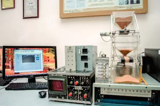
Automated laboratory dosing unit
This model allows you to explore and improve dispensing methods on the basis of identification and test methods and multivariate measurements.
The laid down algorithms and methods are implemented using the ADC board and Native Instruments software in the LabVIEW functional simulation environment. The physical input/output signal contacts of the machine are looped together and switched to the Siemens S7-400 industrial controller for debugging algorithms. Which allows the development of application software directly in industry-standardized languages and control equipment.
This unit allows to realize different modes of application of test influences (Fig. 3), which allow to evaluate metrological characteristics and to adjust the dispensing process according to new conditions: once testing (distributed tests); repeated testing (pulsating test); alternating testing.
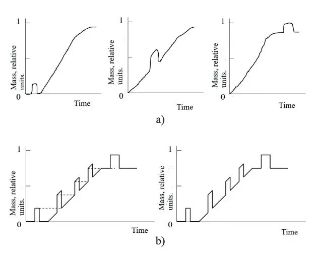
Testing modes: a) once; b) repeated
It is possible to set and solve typical problems of industrial metrology within the framework of the developed unit integrated into the training and research complex of metrology and technical measurements [14]. It includes training problems (figurative dynamic representation and classification of mass measurement methods, identification and test metrological diagnostics, joint discretization of dynamic signals and transducers, joint selection and adjustment of ADC and anti-substitution filters, anti-inertial correction of dynamic signals, multi-criteria selection of metrological solutions, etc.).
V. I NDUSTRIAL I MPLEMENTATION
Using of different technologies depends on the required accuracy of the measuring and dispensing processes, varying in their complexity and cost. However, with a huge volume of production, even a small error over time turns into a significant economic loss. In order to avoid this it is necessary to combine effective methods and algorithms of metrology, control algorithms and technical solutions.
In any production, sooner or later there is a task of batching or weight accounting in some form - continuous batching, batch, multi-component, single-component, etc. In the coal enrichment industry this is the task of burdening different grades of coal, dosing reagents in the metallurgical - metering and loading materials into the furnace pockets, in the chemical industry is the actual task of packing soft containers such as Big-Bag, etc.
Experience shows that the best results can be obtained with automatic dosing complexes. For example, on fig.4 presented dispenser LLC UK «Sibtenzopribor», developed in accordance with the standard GOST 30124-94.
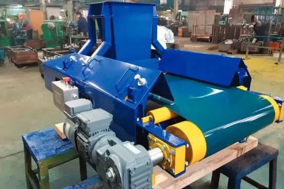
Batch weigher for bulk materials
The batch weigher is an equipment with a complex automated control mechanism, power supply. The construction of the equipment consists of a belt conveyor with a load-receiving device, a control system located in the control cabinet and providing the results of processing, displaying and storing the measurement information, as well as of the drive motor of the belt conveyor. For multi-component dosing, entire systems are being developed, including both individual batch weigners and groups of ones. Fig. 5 shows the dosing window of the charcoal concentrate of the possible 5 components.
The requirements for suppliers of coal concentrate include not only the shipment of the required amount of concentrates of individual coal grades, but also concentrates of different coal grades in a given ratio. This requires the development of automatic control systems that take into account the peculiarities of receipt and distribution of different types of concentrate in the warehouse of finished products, the location of batchers of mixture components, the characteristics ofcollecting conveyors and places of installation of measuring devices. By considering such factors, the control object model is a time- and space-distributed structure with different application points of control actions and different delays for different mixture components [15, 16].
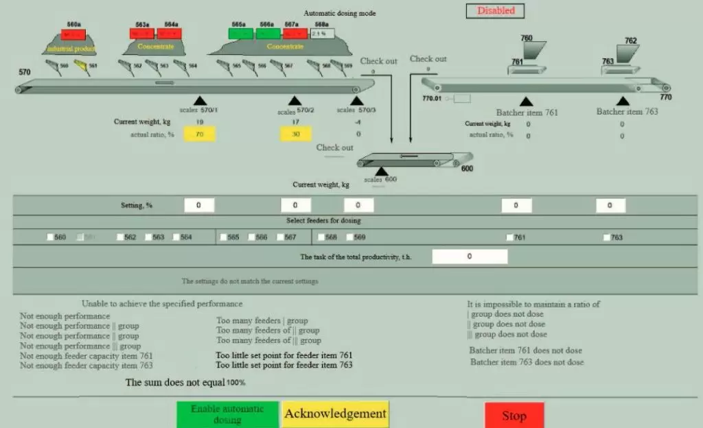
Multicomponent dosing window
Batchers with measuring devices are represented by typical automatic control system`s elements: a relaxation circuit of the first order and an integrating element with cut-off. The total amount of dosed concentrate is evaluated indirectly by summing up the masses of individual mixture components.
The control algorithm includes the following blocks:
-
calculation of the error (error) of dosing the total mass of the mixture;
-
evaluation of the fulfillment of the specified mass ratios of the mixture components;
-
calculated recovery of the required values of each component of the mixture;
-
extrapolation to the lag intervals determined by the location of the batchers relative to the collecting conveyor;
-
generating tasks for the actuators of each batcher.
Similar automatic dosing systems with the presented algorithm are implemented at coal preparation plants. The operating results confirmed the efficiency of the systems [17-19].
VI. СONCLUSION
The results of the work allow us to conclude on the expediency of wide application of the considered direction of technological measurements, which leads to a very significant effect on flexibility, accuracy and diversity of the real measuring process.
Built-in metrological units of identification and test measuring systems with multivariant algorithmic data processing allow combining verification and working measurements, providing reduction of labor costs for maintenance and on-line accumulation of reliable information on their actual characteristics.
The common use of the developed technical and algorithmic solutions makes it possible to create effective automatic dosing systems in various industries.